
5-Jan-2026
Technical Specification and Application Overview: 30-Ton Double Girder Overhead Crane for Heavy Industrial Construction
1. Product Overview and Design Philosophy
In the field of heavy industrial construction, such as the new construction or expansion of steel mills, the reliability, safety, and efficiency of material handling directly impact the overall project schedule, cost, and safety. The 30-ton double girder overhead crane, as a core lifting device in such scenarios, is designed to transcend basic hoisting functions, aiming to become an efficient, reliable, and durable foundational tool in project construction. The standard model provides powerful core performance while ensuring the best cost-benefit ratio. Its design philosophy revolves around “robustness, precision, and strong adaptability.” It is not a specialized device for extreme conditions but offers a proven, universal solution for a wide range of heavy industrial construction projects with typical requirements.
This crane model strictly adheres to internationally recognized mechanical design standards (such as FEM 1.001, ISO 4301, or CMAA 70/74). Its duty class corresponds to A5/A6 (or M5/M6), indicating its suitability for busy mechanical assembly workshops, maintenance workshops, and heavy equipment installation sites with moderate to high load rates. This classification ensures the crane can withstand a certain number of stress cycles within its expected service life, meeting the full-cycle demands from structural installation to equipment lifting during steel mill construction.
2. In-Depth Analysis of Core Parameters and Performance
The core capability of the crane is defined by its key parameters, which collectively determine its applicability to specific projects.
- Lifting Capacity and Span: The rated “30-ton” capacity refers to the maximum net load the crane can safely and steadily lift within a specified span and lifting height range under standard configuration. This capacity covers the vast majority of critical lifting tasks in steel mill construction, such as large H-shaped steel columns and roof trusses (typically weighing 10-25 tons per piece), rolling mill stands (weighing 20-30 tons or more), large motor sets, transformers, and core components of smelting equipment. Span, as another fundamental parameter, defines the crane’s lateral coverage. The standard span range of 15 to 35 meters can adapt to various building layouts, from narrow material transfer passages to spacious equipment assembly halls. Selecting the appropriate span is crucial; it must match the column spacing of the building and ensure the hook can cover all key work areas, such as directly above equipment foundations, material storage areas, and assembly stations.
- Lifting Height and Speed Control: The lifting height is the vertical distance from the hook tip to the floor or rail top. It must be precisely calculated based on the building’s clearance height, equipment placement level, and any underlying structures it may need to pass through. In steel mill projects, the height must consider future maintenance needs, such as lifting out large rotors or rolls. The standard lifting height can be customized according to requirements, with a common range starting from 10 meters to over 30 meters. Regarding speed control, modern standard models commonly use Variable Frequency Drive (VFD) technology. The VFD system enables smooth speed regulation for hoisting, bridge, and trolley travel by smoothly adjusting the motor’s power frequency. This offers multiple advantages: extremely smooth starting and stopping, greatly reducing load swing and allowing operators to precisely position heavy equipment onto foundation bolts; enabling “inching” operations at very low speeds, which is indispensable for precise alignment; and reducing impact loads on mechanical structures and transmission components through soft starting, thereby lowering maintenance requirements.
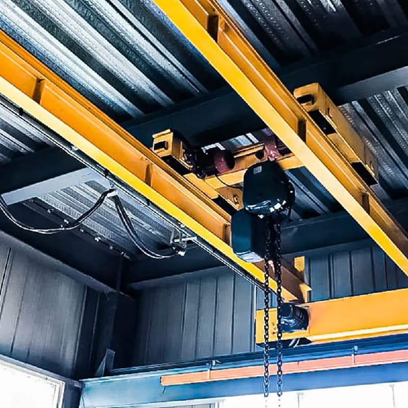
- Structure and Mechanical System: The double girder structure is the cornerstone of this model. Compared to a single girder design, the double girder provides higher vertical and horizontal rigidity, resulting in less deflection when the main girder is under full load. Reduced deflection means smoother trolley travel, more uniform rail wear, and better long-term positioning accuracy. The main girder typically uses an optimized box-type design, balancing strength with controlled weight. The end truck design must consider wheel load distribution and drive configuration to ensure smooth crane travel on the runway rails without slipping or rail gnawing. The hoisting mechanism, as the core, usually features redundant design, such as a dual braking system (service brake and safety brake), and utilizes wire ropes and hook assemblies that comply with international standards.
3. Specific Application Scenarios in Steel Mill Construction Projects
A 30-ton double girder overhead crane plays different critical roles across various stages of a construction project, with its value dynamically reflected as the project progresses.
- Phase 1: Civil Works and Steel Structure Erection: During this stage, the crane is primarily used for erecting the building’s own steel structure. This includes lifting and securing large steel columns onto foundation anchor bolts, hoisting massive roof trusses or beams for high-altitude connection, and installing the crane’s own runway beams. Its high lifting capacity and extensive coverage can significantly accelerate the construction speed of the main structure, reducing reliance on mobile truck cranes, which are often more costly and more limited by site conditions.
- Phase 2: Core Process Equipment Installation: This is the phase where the crane’s value is most concentrated. After the main building structure is completed, various heavy process equipment begins to arrive for installation. The crane is responsible for unloading this equipment from transport vehicles, horizontally moving it near the equipment foundation, and performing the final precise placement. Typical lifted items include: heavy and precision rolling mill stands and housings, large reduction gearboxes, high-voltage motors, components of electric arc furnaces or converters, the main bodies of large dust removal equipment, and heavy fluid pipelines. At this point, the crane’s smooth operation and micro-motion capability are critical; any severe swinging or uncontrolled collision could cause irreparable damage to equipment worth millions. Operators often need to work closely with installation personnel, using wireless remote controls from the best vantage point for millimeter-level precision adjustments.
- Phase 3: Auxiliary System Installation and Future Maintenance: After the main equipment is in place, the crane continues to be used for installing heavy components of auxiliary systems, such as ventilation ducts, cable trays, and hydraulic power unit sets. Upon project commissioning, this crane transforms into a core asset for factory maintenance, used for planned overhauls, such as lifting out motors for maintenance, replacing rolls, or disassembling large valve assemblies for servicing.
4. Available Customization Configuration Options
Although termed a standard model, a range of options is available to adapt to the unique needs and environmental conditions of specific projects.
- Operational Mode Selection:
- Cab Operation: Provides a fully enclosed or open cab with panoramic views, equipped with ergonomic control consoles and air conditioning. Suitable for large workshops requiring prolonged continuous operation or where the operating environment has certain levels of dust or noise, and visibility is good.
- Floor Pendant Control: The operator controls the crane via a cable-connected suspended push-button station. This method is lower cost, and the operator can follow the load’s movement on the floor, obtaining a direct line of sight. It is suitable for situations where lifting routes are not fixed and close observation of the load is required.
- Wireless Remote Control: The operator carries a portable radio remote control, allowing free movement to control the crane from the safest position with the best view. This is particularly advantageous for lifting precision equipment, working in hazardous areas, or when coordination with multiple ground personnel is needed. Many projects opt for a dual “pendant + wireless” control mode for added flexibility.
- Electrical and Safety Add-ons:
- Enhanced Protection Rating: Upgrade the protection rating of electrical cabinets, junction boxes, and drive motors from the standard IP54 to IP55 or higher to better handle conductive dust, moisture, or splashes commonly found in steel mill construction environments.
- Advanced Safety Devices: In addition to standard overload limiters and travel limit switches in all directions, optional equipment includes audible and visual alarms, status indicator lights, anti-collision systems for multiple cranes operating on the same runway, and simple diagnostic systems for monitoring key parameters in real-time (e.g., motor temperature, brake status).
- Power Supply Configuration: Electrical systems can be provided to suit the grid standards of the project location, such as for 380V/50Hz, 440V/60Hz, or other voltage/frequency requirements.
- Mechanical and Lifting Attachment Accessories:
- Main and Auxiliary Hook Configuration: In addition to the main hook (e.g., 30 tons), a smaller capacity auxiliary hook (e.g., 5 tons) can be added to handle simultaneous lifting tasks of varying weights, improving efficiency.
- Specialized Lifting Attachments: Customized lifting beams, spreader beams, or frames can be designed and provided based on the characteristics of the equipment to be lifted, ensuring even load distribution and preventing equipment deformation.
- Environmental Adaptation Design: For outdoor or semi-outdoor projects, basic wind-proof anchoring devices (such as motorized rail clamps or manual rail stops) can be provided.
5. Project Practical Considerations and Trust-Building Factors
When selecting such equipment, customers are concerned not only with specifications on paper but also with the comprehensive support capability behind the equipment.
- Design and Manufacturing Standards: Clear design standards are the cornerstone of quality. Adherence to FEM, ISO, and other norms means that everything from material allowable stress and fatigue calculations to welding procedures and tolerance control follows a rigorous system, ensuring the product’s inherent reliability and predictability.
- Traceability and Quality of Key Components: Customers have the right to know the brands and origins of core components. Typically, key parts such as the hoisting mechanism, motors, frequency inverters, bearings, and wire ropes are sourced from reputable suppliers within the industry. Providing this information helps establish transparency and trust.
- Technical Support and Delivery Documentation: A reliable supplier should be able to provide detailed technical documentation, including general arrangement drawings, foundation load drawings, electrical schematic diagrams, installation instruction manuals, and maintenance checklists. During the preliminary project phase, they should be capable of conducting feasibility assessments and providing recommendations for crane layout based on the initial layout provided by the client.
- Installation Guidance and After-Sales Service: Although on-site installation may be carried out by a third party or the client’s own team, the supplier should provide clear installation guidance and can offer remote or on-site technical support at critical stages (e.g., commissioning). Clear warranty terms, timely spare parts supply channels, and a fault response mechanism are guarantees for long-term cooperation.
Conclusion and Recommendations for Next Steps
In summary, a properly configured 30-ton standard double girder overhead crane is an efficient and long-lasting investment in heavy industrial construction projects. It contributes to the overall success of a project by enhancing operational safety, accelerating the construction speed of the critical path, and reducing dependence on external lifting resources.
To obtain the most accurate technical proposal and quotation, we recommend you provide the following preliminary project information:
- Preliminary layout drawings of the workshop or project, indicating the desired crane service area.
- Required maximum lifting capacity, lifting height, and preliminary estimated span.
- Description of the weight, dimensions, and shape of the heaviest single piece of equipment or material planned for lifting.
- Power supply information at the project location and characteristics of the site environment (indoor/outdoor, dust, temperature, etc.).
- Preferred mode of operation.
Based on this information, our engineering team can prepare a detailed technical proposal for you, including equipment specifications, layout schematic diagrams, and recommendations for customization options tailored to your project, to support your project planning and decision-making.
