
8-May-2026
A 3-Ton Hoist on a 10-Ton Crane? The Engineering Logic Errors That Destroy Overhead Crane Specifications
Introduction: The Inconsistency That Hides in Plain Sight
A procurement engineer at a medium-sized manufacturing plant in South Asia recently sent Dongqi Crane’s application team a request for quotation that read, in part:
“10-ton double-girder overhead crane, 16-meter span, 6-meter lift. To be equipped with our existing 3-ton electric wire rope hoist, which is in good condition and has been inspected. Please quote the crane bridge, end carriages, and electrical system accordingly.”
The request was politely formulated, budget-conscious, and entirely logical from the procurement engineer’s perspective. Why buy a new hoist when a perfectly functional one is sitting in the warehouse? The request was also, from an engineering standpoint, dangerously incompatible with itself. To explain why, and to prevent this same logic error from propagating through procurement specifications across the industry, is the purpose of this article.
The phenomenon of mismatched crane components is far more common than many industry professionals realize. It arises from a natural but flawed line of reasoning: a crane’s capacity is determined by its weakest component, so if I want a 10-ton crane, I simply need to ensure that the hoist, the trolley, the bridge girders, and the runway are all individually rated for 10 tons. By that logic, pairing a 3-ton hoist with a 10-ton bridge is simply a waste of the bridge’s capacity—an inefficiency, perhaps, but not a safety or functionality problem.
This logic is incorrect, and the consequences of acting on it range from premature component failure to catastrophic safety incidents. In the sections that follow, we will dissect the engineering principles that govern crane component compatibility, examine real-world configuration errors that Dongqi Crane’s engineering team has encountered and corrected, and provide procurement professionals with the analytical tools to specify coherent, safe, and cost-effective crane systems.
1. The Matching Principle: Why Crane Components Must Be a System, Not a Collection
An overhead crane is not an assembly of independently rated components. It is an engineered system in which every major element—hoist, trolley, bridge structure, end carriages, wheel assemblies, power supply, and control system—interacts dynamically with every other element under load. The compatibility of these elements is governed by a matching principle that extends well beyond a simple comparison of rated capacities.
1.1 The Design Standard That Embeds the Matching Principle
International crane design standards—including FEM 1.001, ISO 4301, and CMAA Specification 70—do not treat crane components as interchangeable modules that can be mixed and matched at will. They establish a classification system in which every component is assigned a duty class based on two parameters: the load spectrum (how heavy the loads are relative to the component’s rated capacity) and the total duration of use (how many operating hours and load cycles the component will accumulate over its design life).
A critical but often misunderstood consequence of this classification framework is that the overall crane classification is determined by the entire machine operating as a system. The hoist, trolley, crane bridge, and runway each experience the same load spectrum and the same number of operating cycles, but they may be stressed at different fractions of their individual rated capacities. This is where the matching logic breaks down for the unwary.
1.2 The Fundamental Incompatibility: Duty Class Mismatch
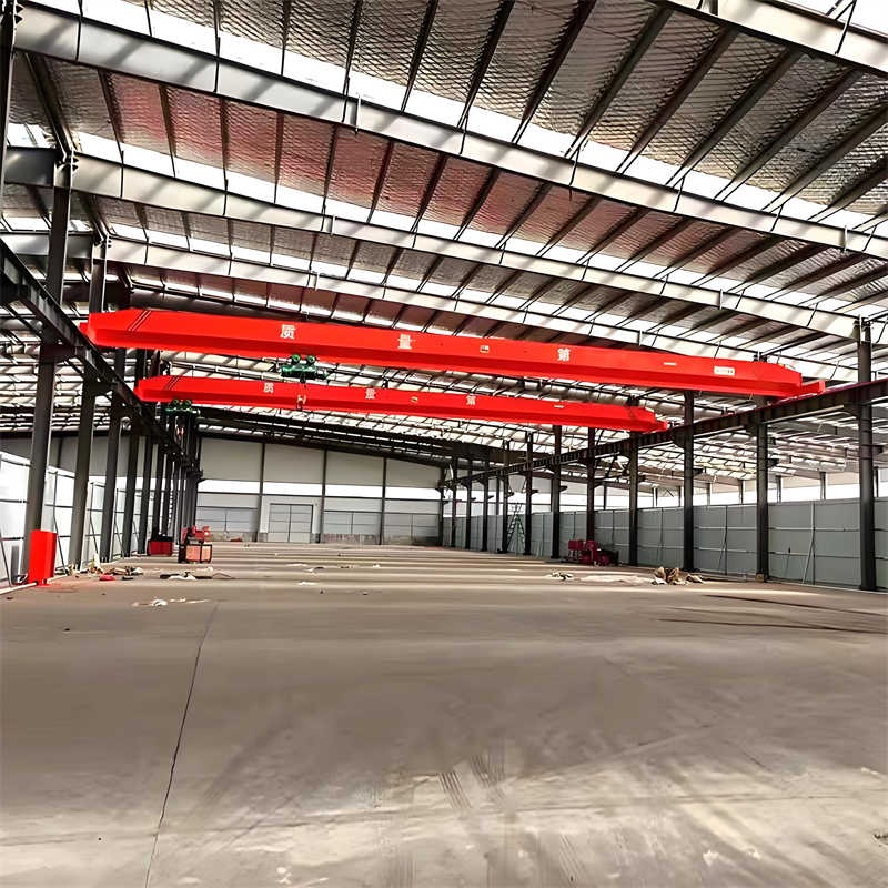
Consider the scenario that opened this article: a 3-ton hoist mounted on a bridge structure rated for 10 tons. The procurement engineer sees this as a capacity mismatch—the bridge is oversized. The engineer’s assumption is that this is wasteful but not unsafe. Let us examine what actually occurs.
The hoist is a 3-ton unit. It is capable of lifting a maximum of 3 tons, and its mechanical components—rope drum, gearbox, brake, motor, rope guides, bottom block, and load hook—are designed, sized, and fatigue-rated for a maximum load of 3 tons. Its duty class, let us assume, is FEM 2m (ISO M5), typical for a general-purpose hoist used in light-to-moderate manufacturing.
The bridge is rated for 10 tons. Its girders, end carriages, and wheel assemblies are structurally sized to carry a trolley with a 10-ton payload rolling along the span. The bridge’s duty class, specified by the client, is FEM 3m (ISO M6), reflecting a heavier intended usage.
When the 3-ton hoist is installed on the 10-ton bridge, the operator will—quite reasonably—lift loads up to 3 tons, since that is what the hoist allows. The bridge therefore operates at a maximum of 30% of its rated capacity (3 tons on a 10-ton structure). At first glance, this seems safe. The bridge is under-stressed.
The problem is not with the bridge. The problem is with the hoist. The hoist is now part of a crane system whose bridge was designed for a higher duty classification—more operating hours, more load cycles, or both—than the hoist itself was designed to handle. The duty class of the overall crane system is determined by the intended application, not by the hoist’s individual rating. If the application demands that the crane operates 16 hours a day with 15 lifts per hour, the hoist—though only lifting 3 tons—is accumulating fatigue cycles at a rate far exceeding its design basis. Its bearings, gears, rope, and structural connections are being consumed at an accelerated pace. The hoist, which appeared “good enough” because it could lift the load, fails years before its expected service life, and it does so not because it was defective but because it was used in an application for which it was never specified.
This is the hidden incompatibility: the duty class of a crane system is a function of the application, not the component ratings. A hoist sized only for the load but not for the duty will be destroyed by the duty.
2. Anatomy of a Mismatch: The Five Dimensions of Component Compatibility
Capacity mismatch—coupling components of different rated tonnage—is the most visible configuration error, but it is far from the only one. Dongqi Crane’s application engineering team has identified five distinct dimensions along which crane components must be matched, and procurement errors frequently occur in all five.
2.1 Capacity Matching: The Obvious Dimension
Capacity matching is the straightforward requirement that the hoist, trolley, bridge, runway, and building structure must all be rated for the maximum load the crane is intended to lift. A 3-ton hoist on a 10-ton bridge is a clear capacity mismatch, but subtler mismatches are common:
- The hoist matches the bridge, but the hook does not. A client orders a 10-ton crane, but the application requires a specialized lifting attachment—a coil grab, a magnet, a spreader beam—that itself weighs 1.5 tons. The 10-ton hoist is now lifting a 10-ton product plus a 1.5-ton attachment, totaling 11.5 tons. The hoist is overloaded.
- The crane matches the product weight but not the process weight. In steel mill operations, the ladle used to transport molten metal can weigh 30% to 50% of the heat weight. A crane specified for the heat weight alone is dangerously under-rated.
- Multiple hoists with different capacities on one bridge. Some applications use a main hoist and an auxiliary hoist on the same trolley. The bridge must be rated for the combined load, not just the main hoist capacity.
Dongqi Crane’s Working Condition Analysis Worksheet captures these distinctions by asking not just “what is the maximum load weight?” but “what is the total weight including all below-the-hook attachments?”
2.2 Duty Class Matching: The Hidden Dimension
Duty class mismatches are the most common and least recognized configuration errors in the crane industry. They occur when components with different FEM/ISO classifications are combined in a single crane system operating under a uniform duty cycle.
Illustrative case: A port facility requires a 20-ton gantry crane for container handling, operating 18 hours per day with 20 lifts per hour and a heavy load spectrum. The correct overall crane classification per FEM is 4m (ISO M7). The procurement team sources a bridge structure rated for FEM 4m from one manufacturer, but to save cost, sources the hoist from a different supplier at FEM 2m (ISO M5) because “it’s rated for 20 tons.” The hoist components—gearbox, rope drum, motor—are not designed for the cumulative fatigue damage of 20 heavy lifts per hour, 18 hours per day. Within two years, the hoist experiences bearing failures and gear tooth pitting that a properly classified hoist would have withstood for a decade.
The Dongqi Crane approach: Our engineering team verifies the duty class of every major component—hoist, trolley, bridge, and end carriages—against the overall crane classification derived from the client’s working condition data. A crane order is not released for manufacturing until this consistency check is complete. We have declined to quote on projects where the client insisted on a component mismatch that we judged would create a safety or reliability hazard.
2.3 Speed and Control Compatibility: The Dynamic Dimension
Hoisting speed, cross-travel speed, and long-travel speed must be matched across the system not just at their maximum values but in their acceleration, deceleration, and control characteristics. A mismatch in speed compatibility creates dynamic problems:
- Hoist too fast for the trolley. A high-speed hoist (say, 12 meters per minute lifting speed) mounted on a trolley with a slow, single-speed cross-travel motor creates a situation where the load is lifted and lowered efficiently but spends excessive time traveling horizontally. The productivity bottleneck shifts to the slowest motion.
- Bridge too fast for the runway. A bridge with high long-travel speed may be incompatible with a runway that was not designed for the dynamic forces generated by rapid acceleration and braking of a heavy crane. Excessive wheel wear, rail spreading, and structural vibration can result.
- Speed mismatch across axes in automated applications. For cranes integrated with automated production systems, mismatched speeds across axes create cycle-time imbalances that reduce overall system throughput even though each individual motion is operating within its specification.
At Dongqi Crane, we specify the full motion profile for every crane axis based on the application’s productivity requirements, then verify that each mechanical and electrical component is rated for the resulting duty. This includes checking motor thermal capacity under the specified acceleration frequency, braking resistor duty cycles, and VFD overload margins.
2.4 Control System Compatibility: The Communication Dimension
Modern cranes increasingly employ variable frequency drives, programmable logic controllers, anti-sway algorithms, and integration with plant-wide manufacturing execution systems. A control system that is not designed to manage the specific combination of hoist, trolley, and bridge drives installed on a crane will produce suboptimal or unsafe behavior.
Common control mismatches include:
- Anti-sway system tuned for a rigid load suspended on short ropes applied to a crane with long ropes and a flexible load. The anti-sway algorithm overcorrects, inducing sway rather than damping it.
- Load-weighing system calibrated for one hoist, but the control system receives signals from a different hoist with different transducer characteristics. The overload protection activates at the wrong load threshold.
- Master-slave synchronization for a multi-hook lift where the drives on different hooks have different speed regulation characteristics. The load tilts progressively during the lift.
- Retrofitting an old hoist with a modern bridge control system. The hoist contactors may not be compatible with the VFD’s control logic, causing hunting, relay chatter, or failure to start.
Dongqi Crane’s standard practice is to supply the complete crane as an integrated electrical and control system. Where a client insists on reusing an existing hoist, our engineering team conducts a detailed control compatibility review before accepting the order. In many cases, the cost of the modifications required to achieve safe, reliable control integration exceeds the cost of a new, correctly matched hoist.
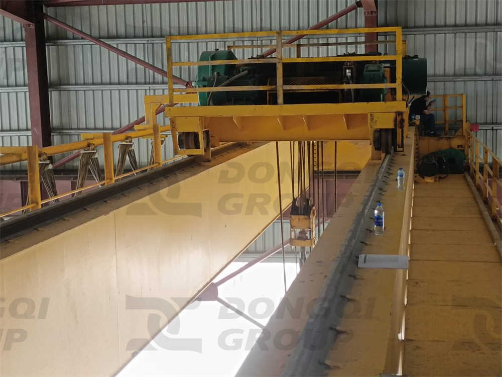
2.5 Power Supply and Infrastructure Compatibility: The Foundation Dimension
A crane’s power supply—festoon cable, conductor bar, or cable reel—must be sized for the total connected electrical load of all motions, not just the largest motor. A power supply system sized for a 3-ton hoist’s electrical demand will have insufficient current-carrying capacity for a 10-ton bridge’s travel motors, even if the hoist itself never exceeds its rated load.
Infrastructure mismatches extend beyond power:
- Runway rail size and wheel compatibility. Crane wheels are designed for a specific rail profile and head width. A crane bridge built for 30 kg/m rail cannot operate safely on 15 kg/m rail without wheel modification or replacement. The wheel flange geometry and load distribution change, potentially causing derailment or excessive wear.
- Runway beam capacity and wheel load distribution. A lightweight crane bridge with concentrated wheel loads may be compatible with the runway beams, but a heavier bridge from a different manufacturer may impose wheel loads that exceed the runway’s design capacity, even though both bridges are rated for the same lifting capacity.
- Building headroom and the hoist’s physical envelope. A low-headroom building may require a compact hoist design. A standard hoist, even if it matches the bridge’s capacity and duty class, may simply not fit within the available vertical space.
3. The Six Most Common Configuration Errors—And Their Engineering Consequences
Drawing from Dongqi Crane’s technical service archives—encompassing thousands of crane installations, retrofits, and failure investigations—we have identified six recurring configuration errors. Each is described with its root-cause logic error and its documented consequences.
Error 1: Under-Sized Hoist on an Over-Sized Bridge
The logic error: “The bridge capacity is determined by the heaviest future load. We will buy a 10-ton bridge now but install a lower-cost 5-ton hoist because our current product only weighs 5 tons. We can upgrade the hoist later.”
Engineering reality: The bridge structure is designed for specific trolley wheel loads and load distributions. A 5-ton hoist trolley has different wheel spacing, different wheel loads, and different axle configurations than a 10-ton hoist trolley. The bridge girder’s local flange bending stresses, web buckling checks, and stiffener positioning are calculated based on the design trolley. Installing a significantly different trolley invalidates these calculations.
If the client later upgrades to a 10-ton hoist, the new trolley may have different wheelbase dimensions. The bridge girders may have been fabricated with stiffeners in locations that do not correspond to the new trolley’s wheel positions. At best, this requires a costly structural reinforcement. At worst, the bridge is incompatible without major reconstruction.
Dongqi Crane’s recommendation: If future upgrade is a genuine requirement, specify a bridge designed for the maximum future trolley from the start, and install a temporary hoist that is geometrically and dynamically compatible with the design-case trolley. We can engineer bridges with upgrade-ready interfaces that minimize future modification cost and risk.
Error 2: Mismatched Duty Cycles Across Components
The logic error: “Duty class is just about the hoist. The bridge just sits there. We can use a lower-class bridge with a high-class hoist to save money.”
Engineering reality: The bridge structure experiences fatigue from the repeated passage of the loaded trolley, from acceleration and braking forces, and from load-induced deflections. An FEM 4m (ISO M7) hoist operating at high cycle frequency may impose fatigue damage on an FEM 2m (ISO M5) bridge structure at a rate two to four times higher than the bridge was designed to withstand. Fatigue cracks in the girder webs, end carriage connections, and diaphragm welds can initiate within years rather than decades.
Furthermore, the bridge travel drives—motors, gearboxes, and brakes—experience starting and stopping cycles at the same frequency as the hoist. A bridge drive system classified for moderate duty will suffer premature brake wear, contactor erosion, and motor insulation degradation when subjected to a high-duty cycle imposed by the application that justified the high-class hoist in the first place.
Dongqi Crane’s approach: We specify the duty class of the entire crane system uniformly based on the application’s operational profile. If the application demands A6 or A7 duty, every major load-bearing and motion component is specified for that classification.
Error 3: The “Reuse the Existing Hoist” Trap
The logic error: “We have a perfectly good 5-ton hoist from the old building. We will design the new crane bridge around it and save the cost of a new hoist.”
Engineering reality: The existing hoist was designed, sized, and certified for a specific application. Its data plate specifies a duty class, a range of permissible spans (if it was part of a monorail system), and design standards that may be decades out of date. Connecting it to a new bridge involves:
- Mechanical interface compatibility. The hoist trolley wheel gauge must match the new bridge girder flange width. Modifying the trolley to fit invalidates the manufacturer’s certification.
- Electrical compatibility. The hoist’s control voltage, contactor logic, and overload protection may be incompatible with modern VFD-based control systems.
- Certification and compliance. In many jurisdictions, reusing an existing hoist on a new crane structure requires recertification of the entire crane—a process that can cost as much as the hoist is worth.
Dongqi Crane’s position: We will evaluate reuse proposals on a case-by-case basis, but our default recommendation is to include a new, correctly matched hoist in the crane supply. The apparent savings of reuse are frequently consumed—and exceeded—by the engineering cost of making the old hoist compatible and the residual risk of operating uncertified or mismatched equipment.
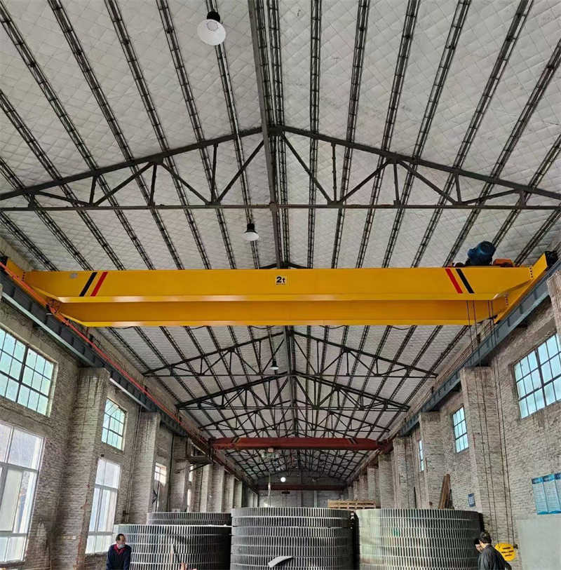
Error 4: Confusing Lift Height with Headroom
The logic error: “The building has 10 meters of headroom, so we can have a 10-meter lifting height.”
Engineering reality: Headroom is the vertical distance from the crane rail level to the underside of the lowest roof obstruction. Lifting height is the vertical distance the hook can travel. Between these two dimensions lies the hoist’s own vertical envelope—the trolley frame height, the hoist body, the distance from the hoist drum centerline to the hook in its highest position. A typical 5-ton wire rope hoist may consume 1.2 to 1.8 meters of vertical space between the rail level and the fully raised hook. The actual maximum lifting height is:
Actual Lift Height = Headroom – Hoist Collapsed Height – Safety Clearance
Procurement requests that confuse these two parameters result in cranes that, once installed, cannot reach the loads they were intended to handle because the hook is too high at its upper limit. The correction—reducing the hoist’s collapsed height by selecting a compact or low-headroom design, or accepting a lower lifting height—must be made before manufacturing, not after.
Error 5: Specifying Span Without Understanding End Carriage Width
The logic error: “The building columns are 18 meters apart, so the crane span is 18 meters.”
Engineering reality: The crane span is the center-to-center distance of the runway rails. The building columns may be 18 meters apart, but the runway rails are mounted on brackets or beams that are offset from the column centerlines. The effective rail span is typically less than the column spacing. Additionally, the crane’s end carriages have a specific wheelbase dimension parallel to the runway. The end carriage width, plus the required clearance between the end carriage and the column or wall at the end of the runway, determines the crane’s approach dimensions—how close the hook can get to the building walls.
Specifying the span incorrectly by even 200 millimeters can result in a crane that does not fit between the runway rails, or one that leaves an excessive gap between the hook’s end approach and the wall, wasting productive floor area.
Dongqi Crane’s working condition analysis includes a detailed building dimensions section that separately captures column spacing, rail centerline dimensions, bracket details, and clear internal building width. Our engineers cross-check these against the proposed crane geometry before design release.
Error 6: Ignoring Power Supply Capacity for the Complete Crane
The logic error: “The facility has a 380V, 100A supply. That is more than enough for a 5-ton crane.”
Engineering reality: A 5-ton crane may seem electrically modest, but the total connected load includes the main hoist motor, cross-travel motor, long-travel motor(s)—potentially two for a double-girder crane with independent bridge drives—plus control power, lighting, and any auxiliary equipment such as a power failure braking system or an air conditioning unit on an operator cabin. When all motors start simultaneously or in rapid sequence, the inrush current can be three to seven times the running current, potentially tripping upstream circuit breakers or causing unacceptable voltage drops that affect other equipment on the same supply.
Dongqi Crane’s standard practice is to calculate the maximum demand load, the starting inrush current, and the allowable voltage drop for every crane we supply, and to verify these against the client’s stated power supply characteristics. Where the supply is marginal, we recommend mitigation measures: soft starters or VFDs with ramp starting, staggered starting sequences, or dedicated supply transformers.
4. A Systematic Approach to Specification Integrity
Preventing configuration errors is not primarily a matter of deeper engineering knowledge on the procurement side—it is unreasonable to expect every procurement professional to be a crane engineer. It is a matter of process: establishing a specification development methodology that forces consistency checks before a purchase order is issued.
4.1 The Single-Source Specification Principle
The most reliable way to ensure component compatibility is to source the complete crane—bridge, trolley, hoist, electrical system, and power supply—from a single manufacturer that takes engineering responsibility for the entire system. This does not mean the manufacturer must fabricate every component internally; most crane manufacturers, including Dongqi Crane, integrate purchased components into their systems. It means the manufacturer’s engineering team has designed the system as an integrated whole, verified compatibility across all interfaces, and certified the complete machine.
When components are sourced from multiple suppliers, the procurement entity itself assumes the role of system integrator—a role that carries engineering liability. This can be managed if the procurement entity has the necessary engineering resources, but in practice, it is the source of many of the errors documented in this article.
4.2 The Working Condition Analysis: Common Data, Consistent Specification
Dongqi Crane’s Working Condition Analysis Worksheet, described in detail in a companion publication, is designed to prevent specification errors by ensuring that every technical parameter is captured once and used consistently across all component selections. The worksheet captures:
- Maximum load weight including all below-the-hook attachments.
- Operational profile (hours per day, days per year, lifts per hour, load spectrum) that determines duty class.
- Building geometry (span, headroom, runway length, obstructions) that determines physical envelope.
- Environmental conditions that determine protection ratings and material specifications.
- Power supply characteristics that determine electrical system configuration.
A single worksheet, completed once and issued to all potential suppliers, forms a common specification baseline. When proposals come back, the procurement team can verify that each supplier has addressed the same requirements—and that no supplier has made incompatible assumptions.
4.3 The Proposal Consistency Checklist
When evaluating crane proposals, Dongqi Crane recommends that procurement teams apply a consistency checklist:
| Check | Question to Verify |
|---|---|
| Capacity consistency | Is the rated capacity of the hoist, trolley, bridge, and hook block identical and equal to the specified maximum load? |
| Duty class consistency | Are the hoist, trolley drives, bridge drives, and structure all classified to the same FEM/ISO duty rating? |
| Speed coordination | Do the hoisting, cross-travel, and long-travel speeds form a balanced productivity profile for the application? |
| Electrical integration | Are all drives, controls, and protection devices from a single coordinated system or verified as compatible? |
| Physical envelope | Does the crane fit within the building’s span, headroom, and end approach clearances with specified margins? |
| Power supply adequacy | Has the manufacturer confirmed that the site power supply is adequate for the maximum demand and starting inrush? |
| Future-proofing | If future upgrades are anticipated, has the proposal specified how the design accommodates them? |
5. The Dongqi Crane Commitment: Engineered Coherence
At Dongqi Crane, we treat every crane we supply as an engineered system, not an assembly of catalog components. This commitment manifests in our standard practices:
Integrated engineering review. Every crane order, whether a standard 1-ton single-girder or a customized 250-ton metallurgical double-girder, undergoes an engineering review before manufacturing release. This review verifies that the specified components are compatible across all five matching dimensions: capacity, duty class, speed and control, electrical integration, and physical envelope.
Single-source responsibility. When Dongqi Crane supplies the complete crane, we accept full engineering responsibility for the system. Our CE certification, ISO quality management certifications, and national special equipment manufacturing license all apply to the complete crane as a tested, verified, and certified machine.
Transparent upgrade pathways. Where a client has a genuine future upgrade requirement, we design the initial crane with documented upgrade interfaces. The bridge structure is sized for the future load. The electrical system has spare capacity and pre-wired connections. The upgrade path is specified in the original documentation, not invented later at the client’s risk.
Refusal to compromise on safety. Our engineering team has, on occasion, declined to quote on projects where the client insisted on a configuration we judged unsafe or fundamentally incompatible. We take this position not out of commercial inflexibility but out of engineering conviction: a crane failure under load can kill people. No commercial opportunity justifies compromising on that point.
Conclusion: Logic, Not Catalog Sizes, Must Govern the Specification
The procurement engineer who asked us to quote a 10-ton bridge for a 3-ton hoist was not acting irrationally. He was acting on a logical assumption—that exceeding the minimum requirement is safe because it provides margin. The assumption was incomplete, not illogical, and our response was to explain the engineering principles that make it incomplete rather than to dismiss the inquiry.
This article has attempted to provide that explanation at a depth that is useful to both procurement professionals and plant engineers. The core message is straightforward: a crane is a system, not a collection of components, and its specification must be governed by system-level logic, not component-level catalog comparisons.
The six matching dimensions—capacity, duty class, speed and control, electrical integration, physical envelope, and power supply—provide a framework for evaluating specification coherence. The six common errors and the consistency checklist provide practical tools for catching mismatches before they become purchase orders and, later, field failures.
Dongqi Crane invites procurement professionals to use these tools in their next crane specification process. Our application engineering team is available to review specifications for internal consistency at no cost, regardless of whether the crane is ultimately ordered from us. Because a properly specified crane—one that operates safely, reliably, and efficiently for decades—benefits the entire industry, not just the manufacturer.
For technical assistance with crane specification or to request a consistency review of your existing crane specification documents, contact Dongqi Crane’s Application Engineering Group.
Henan Dongqi Machinery Co., Ltd. (Dongqi Crane) is a Sino-New Zealand joint venture headquartered in Xinxiang, Henan Province—China’s historic crane manufacturing center. With over 40 years of crane engineering experience, a 240,000-square-meter manufacturing facility, and an installed base in over 96 countries, we deliver European-standard-influenced lifting solutions to the global market. Our certifications include CE, ISO 9001, ISO 14001, ISO 45001, ISO 50001, and GJB9001C.
